Build guide
From one board of OSB to the first listen, in the order you'll do it. The building plan has every dimension; this guide adds the order, the cutting plan and what was learned building and measuring this pair.
| At a glance | |
|---|---|
| Result | a pair of 27-litre vented boxes, 530 × 340 × 254 mm, Aiyima 4" full-range, port tuned to ≈ 48 Hz |
| Material | one 2000 × 1000 mm board of 22 mm OSB, square edges |
| Tools | track or circular saw, biscuit joiner (Flachdübelfräse), drill, Ø 94 / 75 / 70 mm hole saws or a router, clamps and a ratchet strap, stapler, multimeter |
Parts list (per pair)
- 2 × Aiyima 4" full-range driver (8 Ω version)
- 1 × OSB board, 22 mm, 2000 × 1000 mm, square edges (no tongue and groove)
- 1 × HT drain pipe DN75 (75 mm outside, ≈ 71 mm inside), e.g. two 250 mm pieces
- beech strip 15 × 20 mm, ≈ 3.1 m (cleats for the back panel)
- foam gasket tape 3 × 10 mm, ≈ 3.5 m
- 32 × M4 threaded inserts and 32 × M4 × 30 pan-head screws with washers
- 60 biscuits, size 20 (the carcass is glued, no screws)
- 2 pairs of speaker terminals (Ø 12 mm holes)
- sheep's wool fleece (garden fleece / mulch mat, ≈ 10 mm, ≈ 140 g/m², e.g. a 5 × 0.5 m roll): one back-panel sheet and one pocket per speaker
- 2 × 50 g polyester fill (pillow stuffing)
- wood glue (PVA), clear water-based lacquer, acrylic sealant, speaker wire
1 — Cut the board
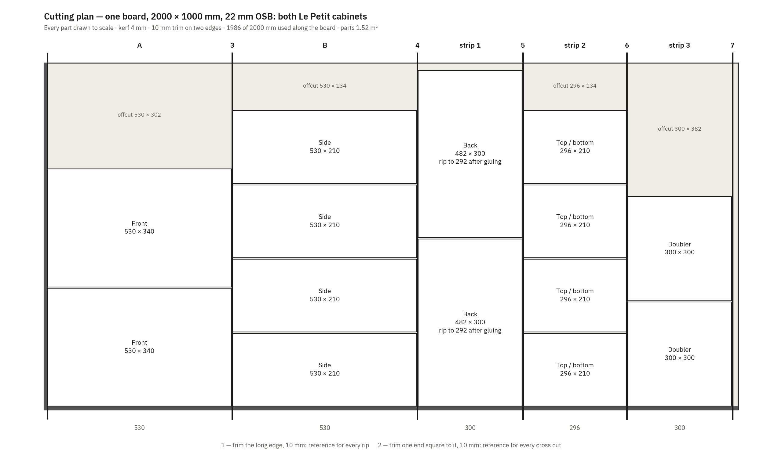
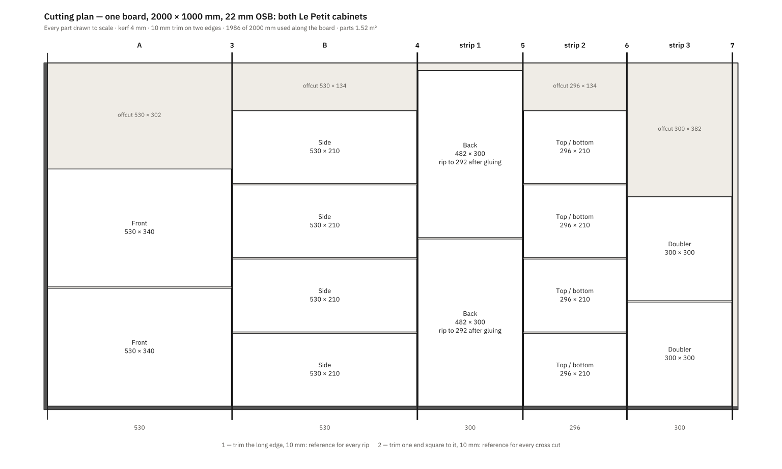
Every part is drawn to scale; 4 mm kerf and 10 mm trim on two edges are included.
- Trim one long edge, 10 mm — the reference for every rip.
- Trim one end square to it, 10 mm — the reference for every cross cut.
- Five cuts straight across the board: 530 · 530 · 300 · 296 · 300.
- Cut each piece up:
| Piece | Cuts | Parts |
|---|---|---|
| Block A | rip 340, 340 | 2 fronts, 530 × 340 |
| Block B | rip 210, 210, 210, 210 | 4 sides, 530 × 210 |
| Strip 1 | cut to length 482, 482 | 2 backs, 482 × 300 — rip to 292 later (step 10) |
| Strip 2 | cut to length 4 × 210 | 4 top/bottom, 296 × 210 |
| Strip 3 | cut to length 300, 300 | 2 doublers, 300 × 300 |
Tips — Measure each width from the edge you just cut, not cumulatively. Cut the four sides and the four top/bottom panels in pairs against a stop. OSB tears out on the exit side: track saw show face up, circular saw show face down. Label every part and mark its show face as it comes off. Strip 1 has only 22 mm to spare: don't trim that long edge.
Downloads: SVG · PNG · generator script
2 — Drill the holes
| Hole | Size | Where |
|---|---|---|
| Driver | Ø 94 mm | front, centred, 115 mm below the top — check against your driver first |
| Port | Ø 70 mm | front, centred, 150 mm above the bottom — same size as the doubler |
| Port | Ø 70 mm | doubler, centre |
| Terminals | 2 × Ø 12 mm | back panel, 40 mm apart (plan sheet 2) |
Chamfer the inside edge of the driver cutout so the cone can breathe. The Aiyima 4" fitted the Ø 94 mm cutout.
3 — Seal the inside faces
OSB is porous and not airtight. Two coats of thinned lacquer on every inside face before assembly; size the cut edges with thinned PVA and let it tack before gluing. A leaky box detunes the port.
4 — Glue the cleats
Glue the beech cleats (2 × 486 on the sides, 2 × 266 between them on top and bottom) with their face 23 mm in from the rear edge — 22 mm back panel + 1 mm compressed gasket. Jig: lay a back panel on the rear edges with 22 mm offcuts plus 1 mm of card underneath as spacers.
5 — Biscuit slots and carcass
The carcass is glued with biscuits — no screws. 30 biscuits per cabinet, size 20:
| Joint | Biscuits (mm from the panel end) |
|---|---|
| Front onto the sides, 530 edges | 6 per edge at 45 / 133 / 221 / 309 / 397 / 485 |
| Front onto top and bottom | 3 per edge at 70 / 170 / 270 |
| Sides onto the ends of top and bottom | 3 per edge at 45 / 105 / 165 |
Size the cut edges with thinned PVA and let it tack, then glue sides, top and bottom with their biscuits. Check the diagonals; a back panel dry-fitted on wax paper holds it square.
Biscuits in OSB — reference the joiner from the face (both parts face down on a flat surface), not from the fence: OSB varies in thickness. Check every slot for voids between the chips and move it 20 mm if it's hollow. Keep sealer and lacquer out of the slots. Clamp harder than usual — ratchet strap plus cauls.
6 — Front and doubler
Glue the front on with its 18 biscuits, strap and cauls across the front. Glue the doubler flush with the bottom edge, 20 mm in from each side; a 70 mm pipe offcut through both port holes locates it.
7 — Seal the corners
A bead of acrylic sealant or a glue fillet in every inside corner.
8 — Finish
Sand 80, then 120 only — the resin-rich chips are harder than the binder, finer grits make the surface wavy. Two to three coats of clear water-based lacquer.
9 — Inserts and gasket
Clamp a back panel in place, drill through it into the cleats, set the M4 inserts. Foam gasket on the cleats, not on the back.
10 — Fit the back panel
Rip each back from 300 to its final width after the carcass is glued: measured opening minus 4 mm. Nominal 292 × 482 mm for the 296 × 486 opening — 2 mm play per side. With 1 mm per side (the plan's 294 × 484), OSB thickness tolerance and a box slightly out of square pinch the panel.
Lesson — Build the back with the gasket and screws. During the measurements a friction-fit back leaked, and the leak changed with every refit: the port tuning moved by up to 10 Hz.
11 — Driver and wiring
Driver into the cutout with a thin gasket, terminals in the back panel, wire with enough slack to take the back off. Check polarity is the same on both speakers.
12 — Port tube
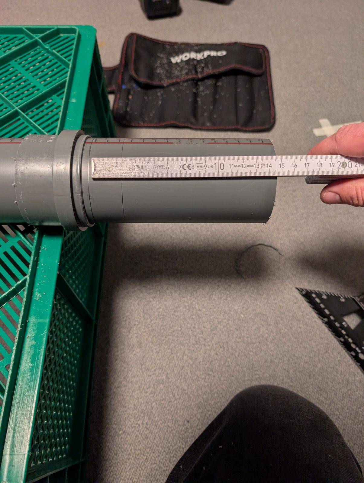
An HT DN75 drain pipe extends the port inside the box. Total port length 175 mm, measured straight through from the tube's inner end to the doubler's outer face. That tunes the box to ≈ 48 Hz — flat bass with the Aiyima (why).
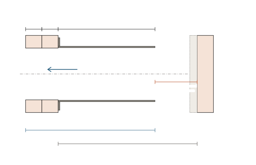
Cut list for the tube: 131 mm tube + 20 mm for the flaps = 151 mm piece.
Both holes, front and doubler, are Ø 70 mm, so the tube (75 mm outside) can't go into the front; it's mounted from the inside: eight 20 mm slits at one end (a 3 mm relief hole at the end of each), the flaps warmed and bent out 90°, four screwed to the inside of the front panel (3.5 × 12 mm), the joint sealed airtight. The plan drew a Ø 75 bore in the front with the tube pushed in — with Ø 70 in both panels the port is one clean bore from the outside to the tube.
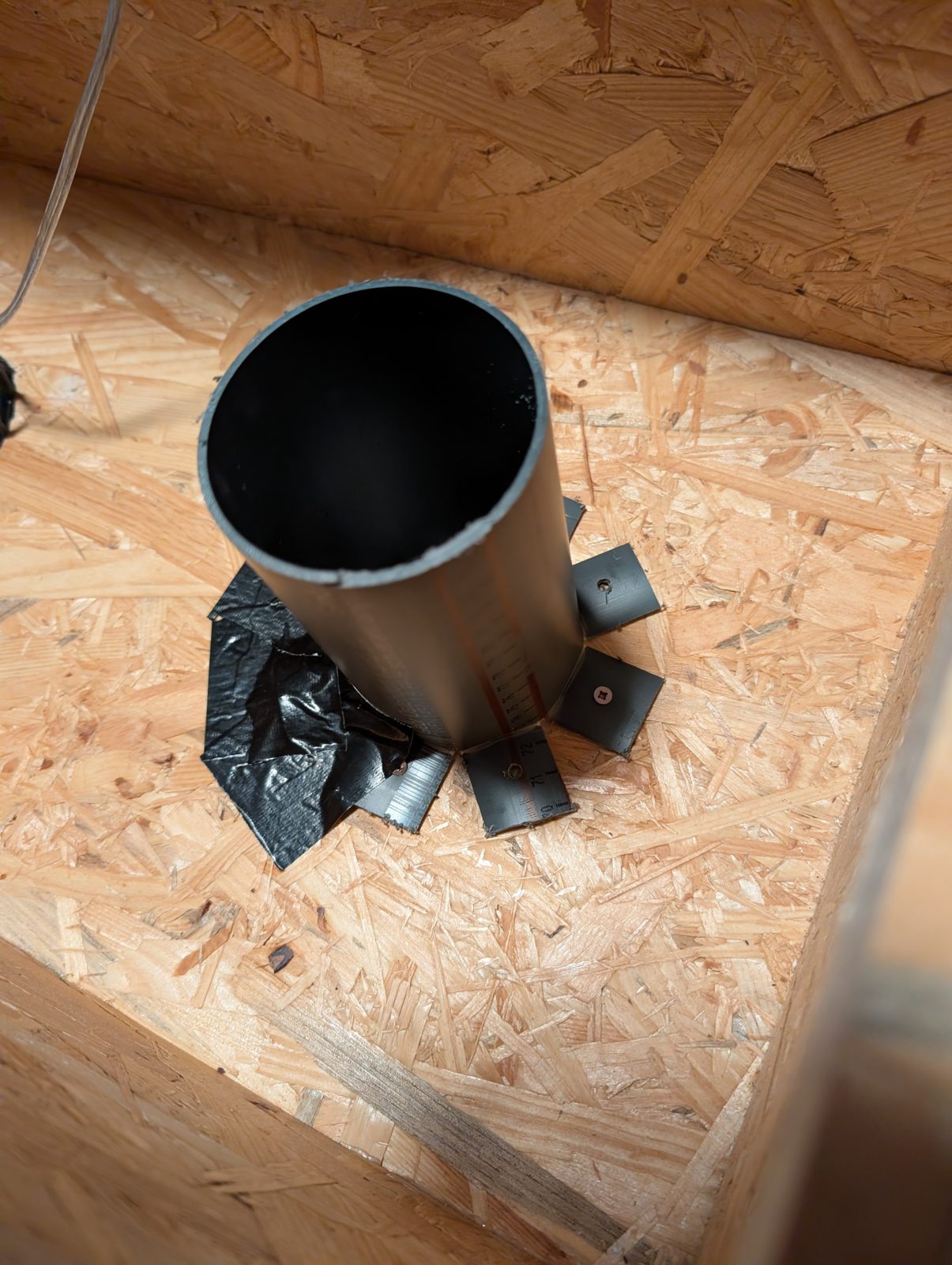
Tip — The tube ends ≈ 4.7 cm from the back-panel wool. Keep that space free; if you hear port noise ("chuffing") at high volume, trim 10 mm (Fb rises by 1–2 Hz). The plan's 117 mm tube (43 Hz) is for the Fostex FE103NV2.
13 — Damping
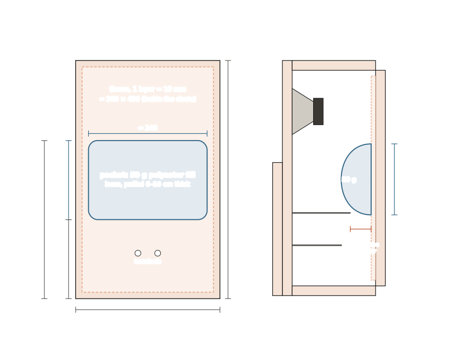
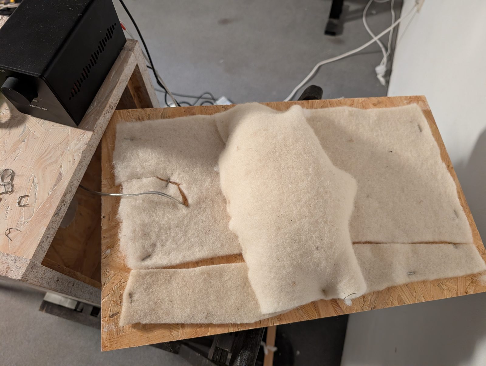
- One layer of sheep's wool fleece (≈ 10 mm) covering the inside of the back panel, opposite the port.
- A wool pocket with 50 g of loose polyester fill, puffy, across the middle third of the box height (≈ 16–32 cm above the inner floor), stapled to the back panel.
Keep ≈ 5 cm clear around the tube's mouth and behind the driver. Materials: sheep's wool garden fleece (≈ 10 mm, ≈ 140 g/m²) and polyester fibre fill — the synthetic stuffing found in ordinary pillows.
The photo shows the test setup, not a finished interior: this layout came out of eight measured variants where material was added and removed between measurements (Damping). For the finished speaker, cut the fleece to the panel, sew the pocket and fix both securely.
14 — Close it and listen
Screw the back on (16 × M4). If you use a DSP, set a protective high-pass at ≈ 0.75 × Fb (36 Hz here): below the port tuning the cone is unloaded. Start at a low level.
Optional, but worth it: measure the impedance with a 50 Ω jig before you close the box for good. It confirms the port tuning and catches a leaking box in two minutes.