Impedance jig
Part of How it was measured — optional reading. To build the speaker you only need the build guide.
The single most useful tool in this project: a resistor and two jack leads that measure the port tuning (Fb) to about ±1 Hz, independent of the room. It also identifies the driver (4 Ω or 8 Ω version) in seconds.
How it works
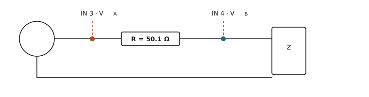
The interface's headphone output drives the speaker through a sense resistor R. Input 3 records the voltage before the resistor (VA), input 4 the voltage across the speaker (VB). With G = VB/VA (estimated from the cross-spectrum, so the shared latency cancels):
Z = R · G / (1 − G)
A vented box shows two impedance peaks; the dip between them is Fb, the port tuning.
Parts
| Part | Notes |
|---|---|
| Sense resistor, ≈ 50 Ω | here 2 × 100 Ω in parallel = 50.1 Ω (measured). Anything 33–100 Ω works; ¼ W is plenty (≈ 20 mW). Orientation doesn't matter |
| 6.35 mm stereo jack → 2 × RCA Y-cable | into PHONES; the white (left) RCA is used |
| RCA → crocodile-clip lead | centre = signal, shield = ground |
| 2 × 6.35 mm mono jack → crocodile clips | the probes into INPUT 3 and INPUT 4 (red = tip, black = sleeve) |
| Multimeter | to measure R and check the wiring |
Wiring: three points
| Point | What connects |
|---|---|
| A (one end of the resistor) | RCA centre (headphone left), INPUT 3 red |
| B (other end of the resistor) | speaker wire 1, INPUT 4 red |
| Ground (speaker wire 2) | RCA shield, INPUT 3 black, INPUT 4 black |
Check with the multimeter before plugging in (jacks unplugged): A↔B ≈ 50 Ω, B↔ground ≈ the driver (≈ 7.6 Ω here), A↔ground ≈ 58 Ω. Never connect the amplifier's speaker terminals to the jig or the interface — the A70 is a bridged amp, both terminals are live.
Settings and calibration
- INPUT 3 and 4: LINE, PAD off. GAIN 3 and 4 fully anticlockwise — the end stops guarantee equal gains (matching them by eye gave 3–6 dB mismatch).
- Level with the PHONES knob; phantom power off; amplifier disconnected.
- Calibrate once: with the speaker unclipped (no current flows) both inputs see the same voltage; the software stores the residual difference and divides it out of every later run. Here: −0.10 dB. Valid as long as GAIN 3/4 stay at their stops.
Verification
A 10.1 Ω resistor (multimeter) in place of the speaker read 10.16–10.24 Ω, flat from 10 Hz to 5 kHz, phase 0° — under 1 % error, including the clip leads.
Reading Fb — and when not to
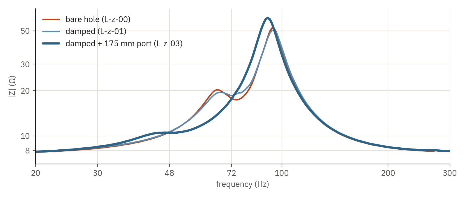
- Bare hole, untreated: clear double peak, dip at 74.4 Hz. The upper peak far taller than the lower one showed the box tuned low for this driver.
- Damped: dip ≈ 72 Hz, only ~1 Ω deep — the fill adds losses.
- With the 175 mm port: the lower peak and the dip shrink to a plateau at 45–50 Hz. The port resonance is heavily damped (fill, wool near the tube's mouth); taping all seams changed little, so it isn't a leak. In that case read Fb from the port near field (its peak, 47.6 Hz here), and use the impedance as the cross-check.