Building plan
Le Petit after Jean Hiraga (L'Audiophile no. 29, 1983), hole positions after R. Berchtold (2022), adapted to 22 mm OSB, butt joints with biscuits and wood glue (no screws in the carcass) and a removable back panel. All dimensions in mm. The drawings are vector files (SVG) — open them full size to print at any scale.
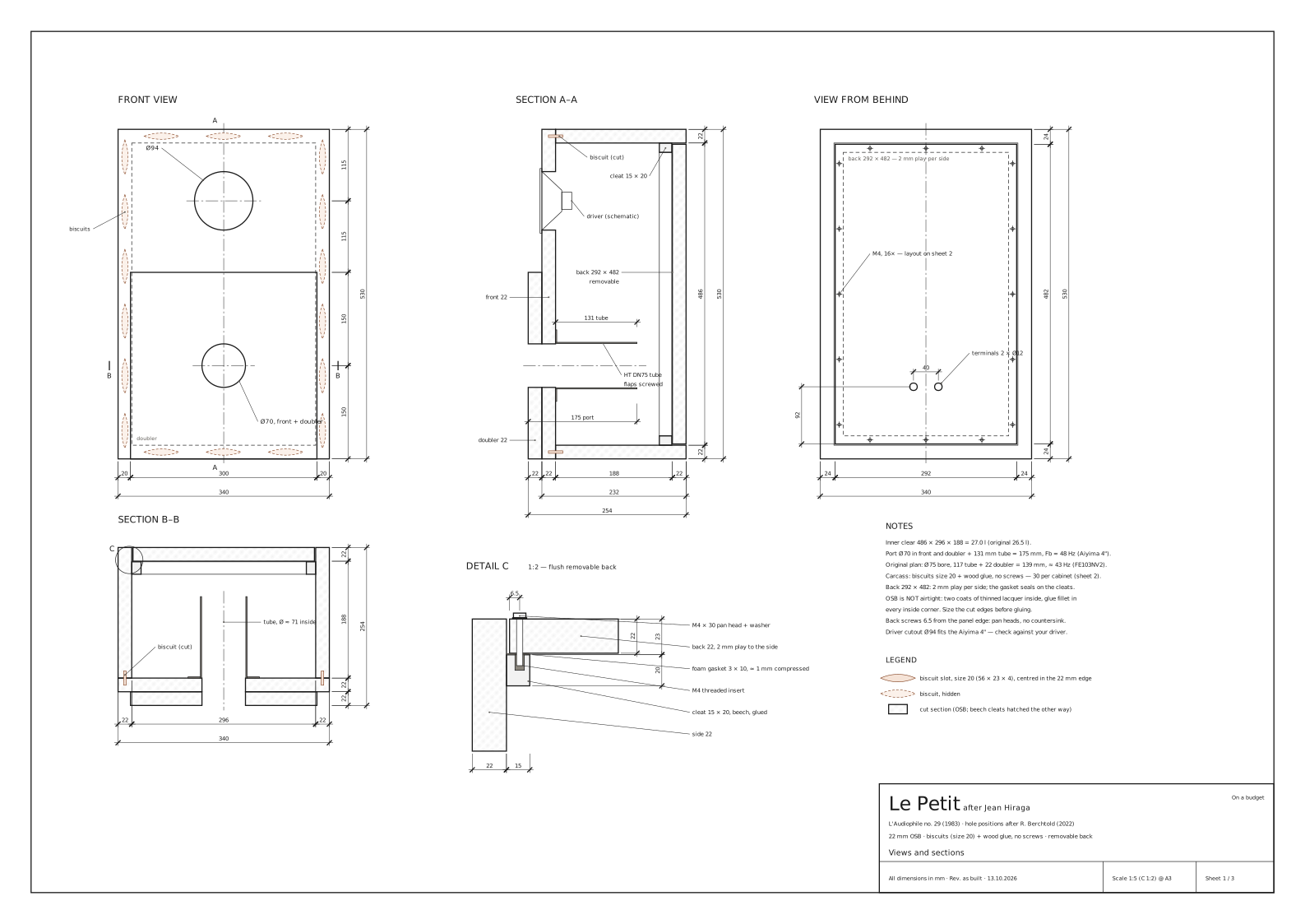
The sheets show the speaker as built: biscuit joints (every slot on sheet 2), the back panel 292 × 482 (2 mm play per side in the 296 × 486 opening), the port Ø 70 in the front and the doubler with a 131 mm tube on screwed flaps (175 mm total). Changes against the original plan: carcass screws → biscuits, back 294 × 484 → 292 × 482, front bore Ø 75 → Ø 70, tube 117 → 131 mm. The sheets are drawn by make_building_plan.py.
Sheet 1 — Views and sections
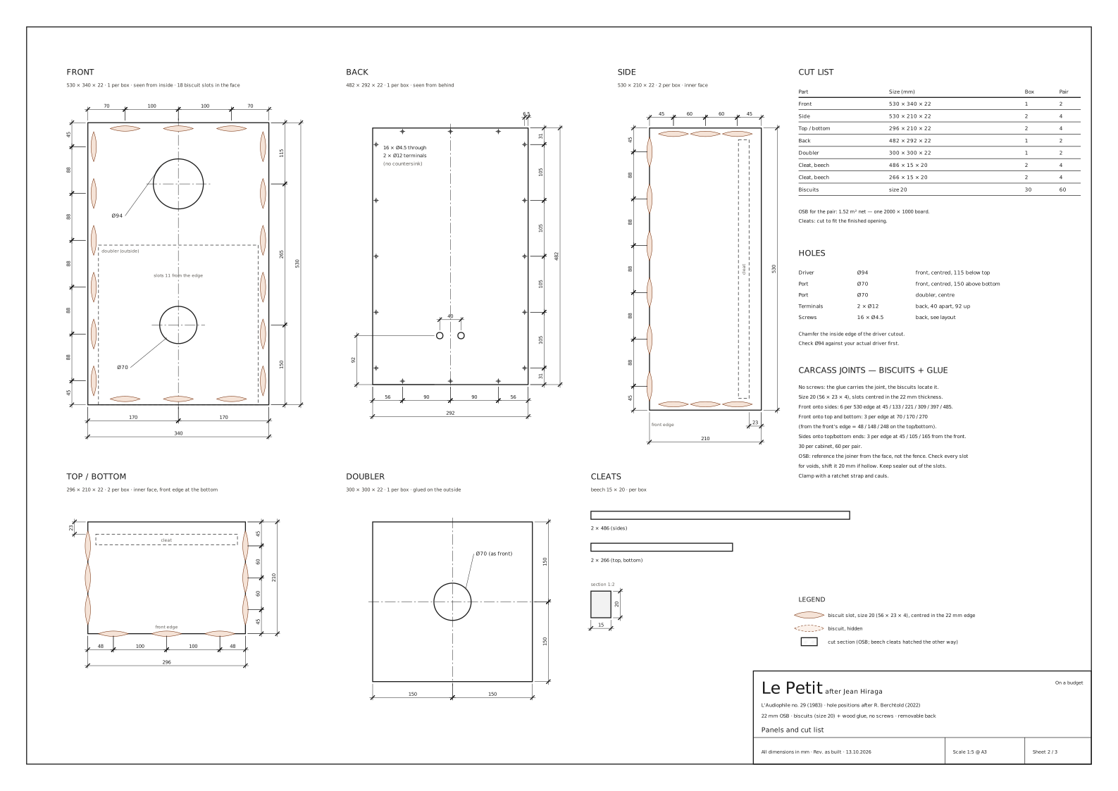
Sheet 2 — Panels and cut list
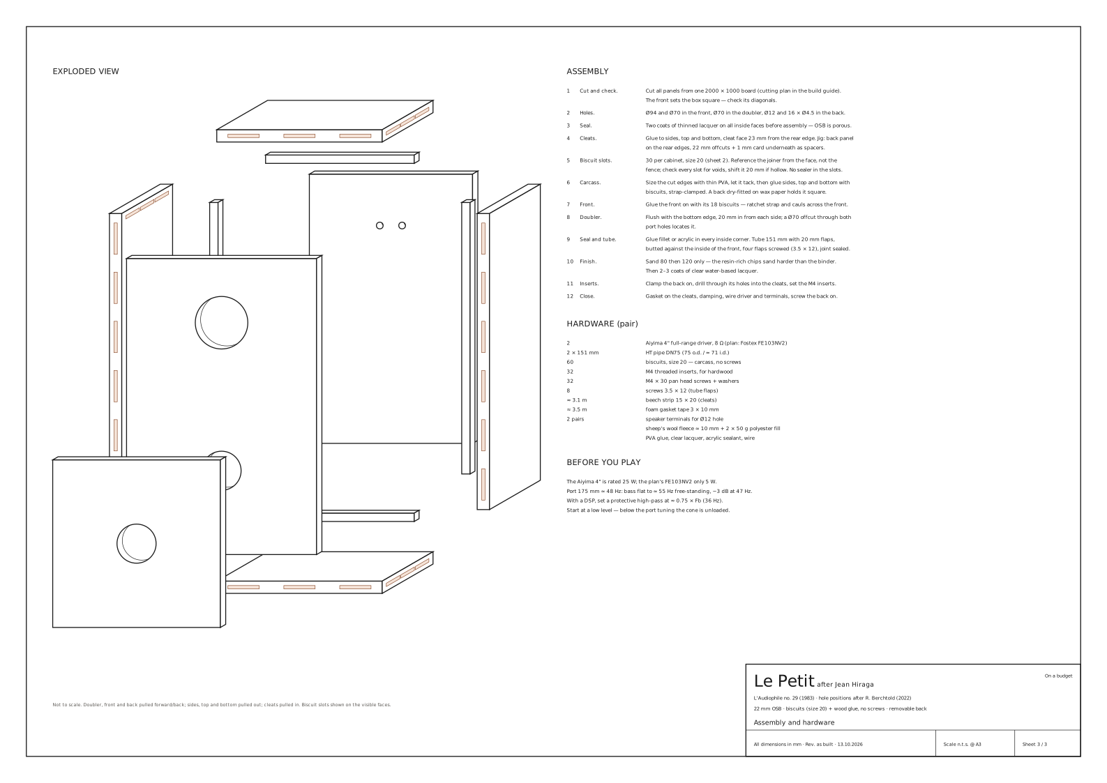
Sheet 3 — Assembly and hardware
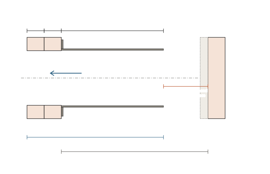
Port (as built)
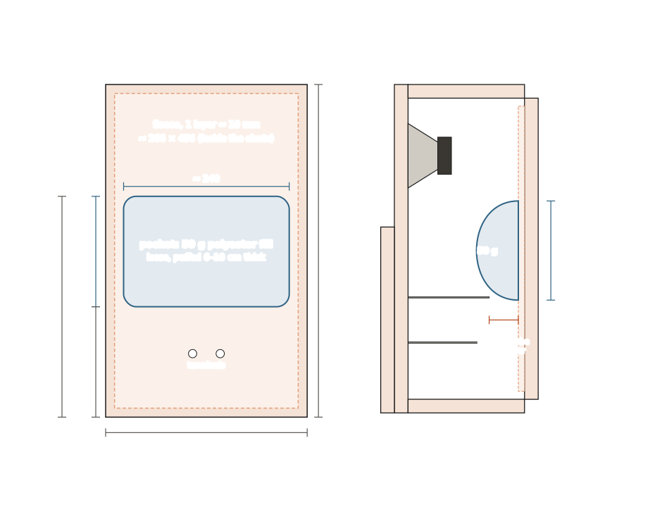
Damping (as built)
Dimensions
| Size | |
|---|---|
| Outside | 530 × 340 × 232 (H × W × D), 254 deep at the doubler |
| Inside clear | 486 × 296 × 188 = 27.0 l (original 26.5 l) |
| Material | 22 mm OSB, butt joints with biscuits (size 20) and wood glue — no screws in the carcass; only the back panel is screwed (M4 into inserts) |
| Port | Ø 70 through the doubler and the front (the original plan: Ø 75 in the front); the plan's tube 117 + doubler 22 = 139 mm ≈ 43 Hz for the FE103NV2 — with the Aiyima: 175 mm total, ≈ 48 Hz (Step 2) |
Cut list
| Part | Size | Per box | Per pair |
|---|---|---|---|
| Front | 530 × 340 × 22 | 1 | 2 |
| Side | 530 × 210 × 22 | 2 | 4 |
| Top / bottom | 296 × 210 × 22 | 2 | 4 |
| Back | 482 × 292 × 22 | 1 | 2 |
| Doubler | 300 × 300 × 22 | 1 | 2 |
| Cleat, beech | 486 × 15 × 20 | 2 | 4 |
| Cleat, beech | 266 × 15 × 20 | 2 | 4 |
| Biscuits | size 20 | 30 | 60 |
OSB for the pair: 1.52 m² net — one 2000 × 1000 mm board (cutting plan). Cut the cleats to fit the finished opening.
Holes
| Hole | Size | Position |
|---|---|---|
| Driver | Ø 94 | front, centred, 115 below the top — check against your driver first |
| Port | Ø 70 | front, centred, 150 above the bottom — same as the doubler |
| Port | Ø 70 | doubler, centre |
| Terminals | 2 × Ø 12 | back, 40 apart, centred, 92 up — not critical |
| Back screws | 16 × Ø 4.5 | through the back, no countersink: 56 / 90 / 90 / 56 across, 31 / 105 / 105 / 105 / 105 / 31 up, 6.5 from the edge |
Chamfer the inside edge of the driver cutout.
Carcass joints: biscuits and glue
As built, the carcass is glued with biscuits — no screws. Sheet 2 shows every slot. 30 biscuits per cabinet, size 20 (60 for the pair).
| Joint | Biscuits (positions in mm from the panel end) |
|---|---|
| Front onto the sides, along the 530 edges | 6 per edge at 45 / 133 / 221 / 309 / 397 / 485 |
| Front onto top and bottom | 3 per edge at 70 / 170 / 270 |
| Sides onto the ends of top and bottom | 3 per edge at 45 / 105 / 165 |
Biscuits in OSB — what's different from MDF
- Reference from the face, not the fence. OSB varies in thickness and the surface is uneven, so the fence wanders. Lay both parts face down on a flat surface and cut the slots from there. Size 20 in a 22 mm edge leaves about 9 mm of material each side, centred.
- Check every slot before gluing. The cutter can run into a void between the chips; if a slot is hollow, move it 20 mm and cut again.
- Keep sealer and lacquer out of the slots. Saturate the edges with thinned glue beforehand, but the biscuits must swell into bare material.
- More clamping pressure than usual: a ratchet strap plus cauls across the front, or the joints open.
Removable back (detail C)
| Cleats | beech 15 × 20, glued; their face sits 23 from the rear edge (22 back + 1 compressed gasket) |
| Gasket | foam 3 × 10 on the cleats, compresses to ≈ 1 mm |
| Fixing | 16 × M4 threaded inserts in the cleats, M4 × 30 pan-head screws with washers (a countersink 6.5 mm from the panel edge breaks out) |
| Back panel | flush with the rear edge, 2 mm play per side |
Assembly order
- Cut and check. Cut all panels; the front sets the box square — check its diagonals.
- Holes. Ø 94 and Ø 70 in the front, Ø 70 in the doubler, Ø 12 and 16 × Ø 4.5 in the back.
- Seal. Two coats of thinned lacquer on all inside faces before assembly — OSB is porous.
- Cleats. Glue to sides, top and bottom, face 23 mm from the rear edge (jig: back panel on the rear edges, 22 mm offcuts + 1 mm card as spacers).
- Biscuit slots. Cut all 30 slots per cabinet (size 20), referenced from the face; check each for voids.
- Carcass. Size the cut edges with thin PVA, let it tack, then glue sides, top and bottom with biscuits, strap-clamped. A back dry-fitted on wax paper holds it square. Check the diagonals.
- Front. Glue it on with 18 biscuits; clamp with a strap and cauls across the front.
- Doubler. Flush with the bottom edge, 20 mm in from each side; a 70 mm pipe offcut through both port holes locates it.
- Seal and tube. Glue fillet or acrylic in every inside corner; fit and seal the port tube.
- Finish. Sand 80 then 120 only, then 2–3 coats of clear water-based lacquer.
- Inserts. Clamp the back on, drill through its holes into the cleats, set the M4 inserts.
- Close. Gasket on the cleats, damping, wire driver and terminals, screw the back on.
Hardware (pair)
| Qty | Item |
|---|---|
| 2 | full-range drivers (plan: Fostex FE103NV2; this build: Aiyima 4", 8 Ω) |
| 2 | HT pipe DN75 (75 o.d. / ≈ 71 i.d.) — cut to length |
| 32 | M4 threaded inserts for hardwood |
| 32 | M4 × 30 pan-head screws + washers |
| ≈ 3.5 m | foam gasket tape 3 × 10 |
| 2 pairs | speaker terminals for Ø 12 holes |
| 60 | biscuits size 20 (carcass, no screws) |
| damping — plan: 10 mm wool felt (≈ 1.2 m² per pair); this build: sheep's wool garden fleece (≈ 140 g/m²), one back-panel sheet + one pocket per speaker, and 2 × 50 g polyester fill | |
| PVA glue, clear lacquer, acrylic sealant, wire |
Notes on the plan
- OSB is not airtight. Seal all inside faces with two coats of thinned lacquer and run a glue fillet or acrylic bead into every inside corner. Size the cut edges before gluing.
- Cleat face 23 mm from the rear edge: 22 mm back + 1 mm compressed gasket.
- Back screws sit 6.5 mm from the panel edge — use pan heads; a countersink this close to the edge breaks out.
- Damping (plan): 10 mm wool felt on all walls, or 50 mm foam on the floor and lower side walls, which is better against the low box mode. Measured in this build: one felt layer on the back panel plus a 50 g fill pocket at mid-height does the job with one sheet of felt per speaker (Damping).
- Check the Ø 94 driver cutout against your actual driver before cutting.
Before you play
- The plan's FE103NV2 is rated at 5 W — fine with a low-power valve or class-A amp, less fine if someone else reaches for the volume knob. The Aiyima 4" used here is rated 25 W.
- The plan's tuning (≈ 43 Hz) makes the FE103NV2's bass fall off below about 300 Hz; wall or corner placement helps, and a sub crossed at 100–150 Hz takes it further. With the Aiyima and a 175 mm port the bass is flat down to ≈ 55 Hz free-standing (Step 2).
- With a DSP, set a protective high-pass at ≈ 0.75 × Fb (36 Hz for Fb ≈ 48 Hz).